Postingan

Menampilkan postingan dari Oktober, 2011

Solar Charger Circuit by LM317

Gambar
Here is a solar charger circuit is used to charge lead acid batteries or Ni-Cd with solar power. Circuit harvests solar energy to charge a 6 volt battery 4.5 Ah battery for various applications. The charger has voltage and current regulation and voltage cut-off facilities. The circuit uses a 12 volt panel solar energy and a variable voltage regulator IC LM 317. The solar panel consists of solar cells each rated at 1.2 volts. 12 volt DC is available from the panel to charge the battery. Load current flows through D1 to the voltage regulator IC LM 317. By adjusting the adjustment pin, voltage and output current can be regulated. VR is placed between the adjustment pin and ground to provide an output voltage of 9 volt battery. Restrict resistance R3 load current and the diode D2 prevents the discharge of the battery current. Transistor T1 and zener diode ZD act as a cutoff switch when the battery is full. Usually T1 is off and the battery current load. When the voltage at th...

Infrared transmitters using LM3909

Gambar
This is an infrared transmitter circuit of the signal is small and using a power supply of 1.5 V only. by the main electronics are the two LM3909 (oscillator IC LED Flasher) Normally, we tend to put it to work as a simple flashing light circuit. Use a source of low-power 1.5 V, which is working now easier to use transistors. The high frequency is very simple, just change the high frequency device only. C1 and R1 is less than the highest frequency.

60W Class AB Audio Amplifier with TDA7294

Gambar
Here is the circuit diagram of 60W class AB audio amplifier which is built based power IC TDA7294. The TDA7294 amplifier module is a monolithic integrated circuit. It's meant for use as an audio class AB amplifier in hi-fi applications. It has a wide voltage range and output current capability, enabling it to supply the highest power into both 4 ohm and 8n ohm loads. Using the addition of a handful of components and also a appropriate power source, this module will achieve 50W RMS into 8-ohm with 0.1% THD. You have to provide a heavy duty heatsink rated at 1.4°C/W. Pin 10 will be the MUTE input and pin 9 provides you with a STANDBY mode. Muting ought to always take place just before standby mode is used. Connecting these pins permanently to the power supply rail (insert links) makes sure that the amplifier comes on instantly on power up. Extending the time constants R3-C6 and R4-C5 may possibly eliminate any switch-on clicks. The IC has internal thermal protection that causes the...

LM3900 Audio Mixer Circuit

Gambar
LM3900 Audio Mixer Circuit Audio mixer circuit consists of 4 four-channel amplifier (LM3900) two microphone inputs and two audio inputs are available directly online at this circuit. By adding the parallel with this circuit, you can increase the number of entries according to applications. Each input is connected to the inverting terminal of the LM3900. The amplifier built in each section amplifies each audio input separately and fed to the output terminals. The output terminal of each channel is connected to a single output line with a resistance no greater than 680 and produces a mixture of audio output with low noise. This audio mixer circuit does not use a low impedance input sources to the mix of ideals. Capacitors C1 to C4 are decoupling capacitors corresponding channels. C5 is the decoupling capacitor production.

30W Class AB Power Amplifier Circuit

Gambar
30W Class AB power amplifier circuit diagram using power transistor. Set the above amplifier up by adjust the variable resistor R1 to maximum and R12 to zero. After this set up is done, the activate / turn on the amplifier. Adjust the R1 so that the measured output offset is between 30 and 100mV. Once set, adjust the R12 slowly to achieve a quiescent current of around 120mA. Keep checking the quiescent current as the amplifier heats up as it might change due to voltage drop changes in the output devices because of the heat. The heatsinks should be 0.6K/W or less for two amplifiers. Power supply circuit for 30W class AB power amplifier:

TV Remote Jammer Using 555 IC

Gambar
TV Remote Jammer Using 555 IC The TV remote control transmits television signals as pulses of frequency around 37.5kHz. Each button on the remote control is pressed or equivalent has a pulse signal codes. This remote transmits pulses of the circuit block of the same frequency as the remote to your TV confuse decoding the transmitted signal. The heart of the circuit is the 555 timer IC in astable circuit works mode.The output series of pulses at a frequency of 18 kHz to 48 kHz by simply adjusting the 5K potentiometer. What you do is adjust the potentiometer until frequeny jives to its distance from the TV or until the signal is ignored by television.

Simple Emergency LED Light Circuit

Gambar
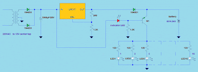
Simple Emergency LED Light Circuit This emergency LED light is simple, inexpensive and easy to build. The circuit to the battery and when the main source is not available, such as brownouts, white LEDs turns on automatically. Initially, the output voltage from 220V to 12V converter is fed to the input of LM317 regulator. Then, this voltage is regulated to 7.37V with 240 ohms and the combination of the resistance of 1.2K (see LM317 Calculator). At this time, the battery is in charging mode and the transistor Q1 is off. LED serves two purposes, one is mainly to give us an idea of ​​the battery is charging and the other is to ensure that Q1 is off. During voltage drops, the transistor Q1 is on and supplies the current to 16 white LED of about 20 mA each, so a fully charged battery (6V/4.5Ah) may last up to 14 hours. The charger has a built in over current control, but still protects the battery from overcharging and charging voltage is at 7.4V only.