Postingan

Menampilkan postingan dari September, 2011

45W Power Audio Amplifier Circuit with HEXFET

Gambar
This is 45W power audio amplifier circuit which built using HEXFET IRF9540 and IRF540. This is a ideal solution for the make a good, low cost power amplifier circuit . Components List: R1 = 47K ohm C1-2-6-7 = 100nF 100V MKT Q5-6 = IRF9540 R2-12 = 1K ohm C3-4 = 22uF 25V Q7-8 = IRF540 R3-4 = 3.3K ohm C5 = 220pF styroflex TR1 = 5K ohm trimmer multiturn R5 = 1.2K ohm C8-9 = 4700uF 63V TR2 = 1K ohm trimmer multiturn R6 = [1.2K ohm] 820 ohm *See text C10 = 1uF 100V MKT F1-2 = fuse 3A R7 = 270 ohm D1-2 = 15V 0.5W zener J1 = 2pin connector 2.54mm step R8 = 220 ohm IC1 = LF411 or AD711 or LF351 J2 = 5pin connector 5mm step R9 = 27K ohm Q1 = BC550C R10-11 = 22K ohm Q2 = BC560C All Resistors 1/4W 1% metal film R13-14-15-16 = 150 ohm Q3-4 = BC547B The preamplifier and the driver support in a operational amplifier [IC1]. The voltage fall in resistors R5 and TR2/R6, drive the output FET's gates and is proportional with the input signal level. Transistors Q1-2 function as voltage stabilizers in ...

40A Stabilized Power Supply Circuit

Gambar
This power supply is designed for amateurs, and has been in operation for over 10 years. Its design is simple and virtually immune to RF. It brings together the individual pieces, is the most expensive of 600 VA toroidal transformer, which can be replaced by another with different characteristics in the case of a voltage between 17 ~ 20V power and adequate for our needs. Reference voltage of 7.5 V Zenner diode (6V8 8V2 ~), shall apply to Q2, which compares the input voltage divider consisting of resistor R5, R6 and VR2, address Darlington amplifier Q3, which is responsible for driving the output stage, which consists of a driver in Q4 2N3771 NPN transistor and 4 power, which can be mounted directly on the heat sink without insulation, since it is a grounded collector. The source has a current limit (Q1), adjusted by VR1 and overload LED (DL2) and full short circuit protection, with zero consumption in case of short circuit can be maintained indefinitely in this state wit...

Fm Wireless Microphone Circuit

Gambar
Easy FM wireless microphone This FM wireless microphone is easy to build and has a large benefit of transmission (about 300 meters, while outdoor). Regardless of its small component count and 3V operating voltage that will easily penetrate the excess of some floors of an apartment development. It can be adjusted everywhere, while in the FM band (87-108MHz) and its transmissions can be picked up at any ordinary FM receiver. The coil (L1) should be about 3 mm in diameter, with five rounds of 0.61 mm copper wire. You are able Tx frequency range by simply adjusting the distance between the coils. The antenna should be half or quarter of an extended wave (100 MHz 150 cm or seventy-five centimeters). FM wireless microphone circuit description: The audio amplifier stage (T1) is a conventional common emitter amplifier. The 47nF capacitor isolates the microphone from the base voltage to the transistor and only allows AC signals to pass. The LC tank circuit T2 occurs, the feedbac...

Power Supply Circuit using IC LM317

Gambar
The primary part of this Power Supply circuit is the voltage regulator IC LM 317. This circuit is ideal for power circuits as the circuit of the power amplifier can deliver a current of 2A. In this circuit the transistor acts as a pass transistor Q1 to increase current capacity. The output voltage is set to 40V by using resistors R5 and R8. Parts List Resistors: R1 (39 ohm 1 or 2W Resistor), R2 (22 ohm 1/4W Resistor), R3 (68K 1/4W Resistor), R4 (220R 1/4W Resistor), R5 (47K 1/2W Resistor). Capacitors: C1 (3300µF 50V Electrolytic Capacitor), C2, C5 (100nF 63V Polyester Capacitors), C3 (10µF 63V Electrolytic Capacitor), C4 (220µF 50V Electrolytic Capacitor). Active Components: D1 (Diode bridge 4A), D2 (1N4002 Diode), D3 (LED any color), U1 (LM317), Q1 (TIP42A Transistor), T1 (230V Primary, 40V 2A, Secondary, mains transformer).

30W VHF FM Broadcast Amplifier

Gambar
The 30 watt amplifier circuit shown below provides an appropriate power boost with an input of 4 watt up to 6 watts. The circuit is designed to cover 88-108MHz FM Broadcast Band. However, the circuit is very stable at my place and provides a clean-output through seven (7) element Butter-worth low-pass filter. The heart of the circuit is 2SC1946A VHF RF power transistor. The transistor is specifically designed to operate at frequencies up to 175 MHz, with very good results. The feedline is decoupled. The current amplifier can be more than 5 amps. All coils are made of 16gauge wire rod (copper or silver wire can do better) and HF RFC may be central torus (as shown in the image) or 6-hole ferrite R1 bead.C3 and snubber circuit forms, while R2 and C6 prevent the amplifier self-oscillation in VHF, it is sometimes necessary to add 180 ohms in parallel with the amplifier will L7.That to dispel UNDESIRABLE VHF thereby reduce the spurious level. The 60Watts VHF power amplifier using ...

5-band Graphic Equalizer using BA3812L

Gambar
This circuit uses a single chip, IC BA3812L to perform a 5-band graphic equalizer for use hi-fi audio systems.The BA3812L is a five-point graphic equalizer that has all the necessary functions integrated into one IC. The IC consists of the five tone control circuits and input and output buffer amplifiers. The BA3812L features low distortion and low noise and wide dynamic range, and is an ideal choice for Hi-Fi stereo applications. It also has a wide range of operating voltage (3.5 V to 16V), which means it can be adapted for use with most music players. The five center frequencies are independently set using external capacitors, and as the buffer amplifier output stage and the tone control section are independent circuits, fine control over the width of a frequency band is possible, BA3812Ls use two, it is possible to build a 10-point graphic equalizer. The amount of boost and cut can be adjusted by external components. The recommended power supply is 8 V, but the circuit ...

Remote Control Circuit using NE555 & LM567

Gambar
Remote control circuit consists of two parts, one is the transmitter and the other is the receiver. A simple schematic diagram of the remote control. IC transmitter transmitter circuit is controlled by NE555. Receiver circuit works by the frequency of the signal, which is emitted by the transmitter circuit. Transmission frequency of the signal must be equal to the decoder frequency receiver circuit. The frequency generated NE 555 is the same as the receive frequency of the IC LM 567. Resistor R1 is a variable receiver to facilitate the adjustment process. The system works well when the circuit is ready. The first step is the optimization through the transmitter is turned on continuously, while the receiver R1 to set the value of being able to detect the signal from the transmitter. The second part is the receiver is controlled by LM 567. The following is a schematic drawing receptor. In the image at the top of each channel is designed with a different frequency. Given the bandwid...

Liquid Level Sensor using 741 op amp

Gambar
This circuit liquid level sensor is using a simple and common operational amplifier IC 741 used as a comparator. When the sensor two-fluid levels (you can use two small pieces of PCB or drivers of some of them) are not found in the fluid of the output voltage of operational amplifier 741 is negative and the T1 is blocked as a result 0 volt voltage resistor R5. If the liquid level sensor is placed in the fluid of the output voltage of operational amplifier 741 is about a few hundred milli-volts and the transistor T1 conducts, which is an output voltage in the resistance around R5 4 volts.

Metal Detector using CS209A

Gambar
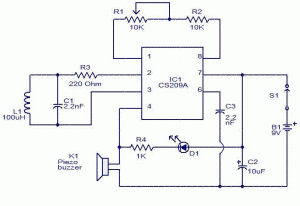
This metal detector using CS209A made by Cherry Semiconductor. The CS209A is a bipolar monolithic integrated circuit for use in metal detection / proximity sensing applications.The CS209A metal detector IC has two on-chip regulators current, the oscillator and low-level feedback circuits, peak detection / demodulation circuit, a comparator and two complementary stages.The oscillator output, along with an external LC network provides controlled oscillations, where the amplitude is highly dependent the Q of the LC tank. The demodulator senses the negative peak of the oscillator wrap and provides a demodulated waveform as input to the comparator. The comparator sets the state of the complementary outputs by comparing the input of the demodulator to an internal reference. The detector is a single coil 100uH. The IC has an oscillator integral part of the strangulation of an external LC circuit is the inductance that is changed by the proximity of metal objects. Is the change i...

TDA2003 on Car Stereo Amplifier Circuit

Gambar
A simple low-power car stereo amplifier circuit based on TDA 2003 is shown here. The circuit uses inexpensive components, readily available and easy to build. TDA2003 is an amplifier of the car radio Integrated ST Micro electronics has a lot of good features like short circuit protection for all pins, thermal in the range of low harmonic distortion, cross low over the distortion. In the circuit here every TDA2003 connected as a mono amplifier operating from a 12V supply. Resistors R2 and R3 form a feedback network that adjusts the gain of amplifiers. C7 is the DC input coupling capacitor C5 couples the speaker to the output amplifiers. C4 is used to improve the rejection wave, while C1 and C2 are used for filtering the power supply. C3 and R1 are used to set the upper cutoff frequency. Network consisting of C6 and R4 is used for frequency stabilization and to prevent oscillation

DC Power Delay based on SCR

Gambar
The circuit diagram shown here is a simple circuit DC power delay , which is based on an SCR (Silicon-Controlled Rectifier) . This circuit is very useful and can be used in many applications. The operation of this circuit is very simple. When input power is applied to the capacitor C2 charges through resistor R2 when the voltage on the capacitor just above the voltage of the Zener diodes D3 breaks, breaks and H1 SCR is triggered and the power delay will be available in late OUT. Notes. The circuit must be assembled on a good quality PCB. The Zener diode must be rated half the input supply voltage. The current capacity of the circuit depends on the SCR and here it is 4A.